

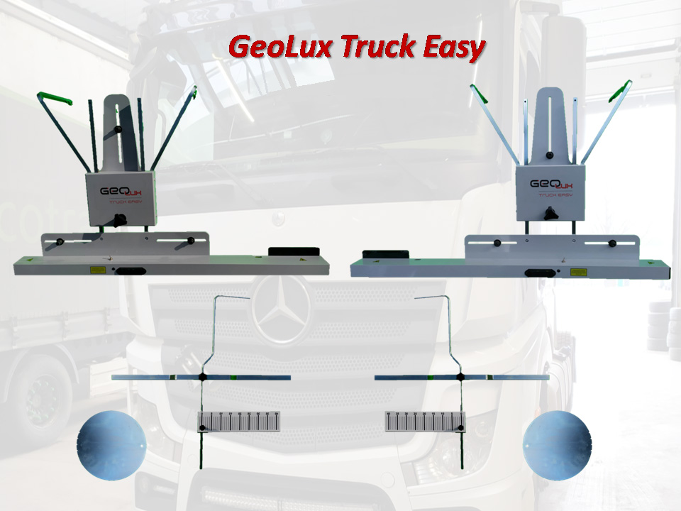
A device for quick measurement of truck and bus wheel alignment
Technical information:
- Max rim diameter 24 inches
- Battery powered: 4 batteries (or accumulators) 1.5V in each head
- Laser: class II, max 1.2 mW
The GeoLux Truck Easy laser device is used to quickly measure wheel geometry parameters of trucks and buses, necessary for their proper driving behavior and minimum tire and fuel consumption.
Standard equipment:
- Left and right measuring heads.
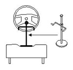
- Suspensions with rear screens left and right.
- Rotating discs 2 pcs.
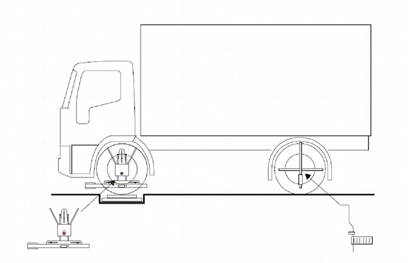
Principle of operation:
Measuring car wheel alignment involves reading the values of horizontal and vertical angles.
The values of horizontal angles are read directly from screens illuminated by a beam of low‑energy laser modules located in the front measuring heads.
The camber angle values are read from a dedicated Android application.
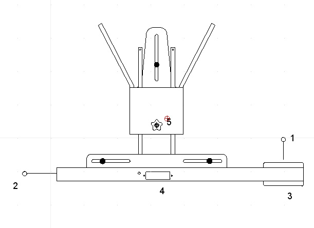
Construction of the front measuring head
- Transverse laser beam for measuring the toe and offset of the front wheels.
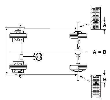
- Longitudinal laser beam for aligning the front wheels with respect to the rear wheels.
- Screen with a scale of wheel alignment and offset.
- Container for 4 AA 1.5V batteries.
- Lock knob.
The left measuring head is a mirror image of the right one.
Conducting a geometry measurement
To ensure correct wheel alignment measurement, the car should be placed in a place that is flat both transversely and longitudinally to the car axle.
The suspension, steering system and wheels should be fully functional before measuring the wheel alignment.
Attachment of the geometry device for measuring the front axle wheels.
Carefully attach the measuring heads to the front wheels and the scales with hangers to the rear wheels. We check whether each of the front head pins touches the rim.
We attach the brake and steering lock (after setting it to drive straight ahead).
Measurement of front axle parameters
After performing the above steps, we can now read the values of the front axle wheel alignment angles, assuming that the rear axle rolling angle is equal to zero.
We set the front wheels so that:
- The readings on the left and right rear wheel centering screens were the same (A = B).
- The wheels were in the straight-ahead position.
In this situation, you can read the toe and camber angles directly.